
A crusher rotor problem can quickly turn into an expensive maintenance decision. Abnormal vibration, repeated wear-part failures, rising bearing temperatures, or visible damage may indicate that inspection is necessary. However, removing the entire rotor assembly does not automatically mean that the complete unit must be replaced.
The real challenge is identifying the source of the problem before committing to a repair or purchasing a new assembly. Replacing worn blow bars or hammers is different from addressing damage to the rotor body, shaft, or bearing interfaces. Overlooking these distinctions can lead to unnecessary spending, repeat failures, and extended downtime.
This crusher rotor removal checklist focuses on what to record during dismantling, how to assess the condition of critical components, and how to use inspection results to make a better repair-or-replacement decision. It is intended for maintenance teams, mining operators, aggregate producers, and distributors managing crusher spare parts.
Important: Crusher designs differ. Always follow the original equipment manufacturer's (OEM) maintenance manual for model-specific removal procedures, lifting arrangements, clearances, and fastener specifications. The guidance below is a general inspection framework, not a substitute for equipment-specific instructions.
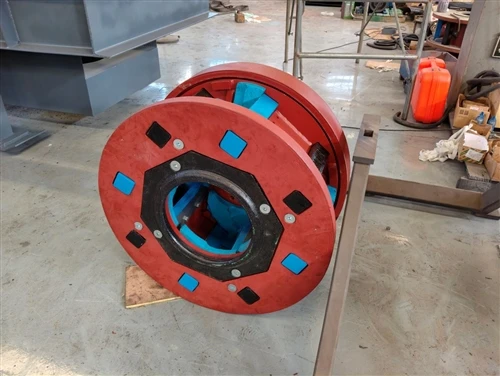
1. Record the Crusher's Condition Before Removal
One of the most common maintenance mistakes is dismantling the rotor before documenting the symptoms. Once components have been removed or cleaned, it may be difficult to identify the original condition or determine what caused the failure.
Before starting work, record the following information:
- Operating symptoms: Note unusual vibration, noise, reduced throughput, uneven product size, or repeated wear-part damage.
- Bearing condition: Record temperature readings, unusual noise, lubrication observations, and any previous bearing replacements.
- Wear history: Document the operating hours or tonnage since the last rotor inspection and the service life of replaceable wear parts.
- Operating conditions: Record relevant changes in feed material, abrasiveness, moisture, feed consistency, or operating settings.
- Visual evidence: Photograph the rotor assembly, wear patterns, damaged areas, fasteners, and surrounding components before dismantling.
Compare these observations with previous maintenance records and the equipment manufacturer's limits. A single high temperature or vibration reading does not establish that the rotor itself has failed. The cause may also involve bearings, the drive system, feed conditions, or material buildup.
The objective is to establish a reliable baseline so the inspection findings can be connected to the original operating problem.
2. Decide What Needs to Be Removed Before Dismantling
Not every rotor-related problem requires complete assembly removal. First identify which component is likely responsible and determine whether the necessary inspection can be completed safely in place.
Replaceable wear parts
Blow bars, hammers, wear plates, or other application-specific wear components may be replaceable without replacing the entire rotor. The exact arrangement depends on the crusher type.
Inspect the wear surfaces for uneven loss of material, local damage, looseness, and differences between corresponding components. Check the applicable manufacturer's wear limits before deciding whether the parts can remain in service.
Rotor body and supporting structure
Damage to rotor discs, the drum, hubs, mounting areas, or other load-bearing sections requires a more detailed assessment. Deformation, suspected cracking, or repeated failures in the same location should not be treated as ordinary wear-part problems.
The rotor may need to be removed to expose critical surfaces, obtain accurate measurements, or carry out non-destructive testing.
Shaft, bearings, and drive interfaces
The rotor shaft and its interfaces connect the assembly to the drive and supporting components. Wear, scoring, fretting, looseness, or damage in these areas can affect fit, alignment, and operating stability.
If abnormal vibration continues after basic checks, inspect the wider system rather than assuming the rotor alone is responsible.
The key principle is simple: define the suspected failure area before choosing the repair scope. This helps avoid unnecessary dismantling while ensuring that safety-critical components receive proper attention.
3. Prepare a Safe and Traceable Removal Process
Before removing the rotor, confirm that the maintenance team has the correct equipment documentation, tools, access arrangements, and lifting plan.
The basic preparation should include:
- Shut down the crusher and isolate all relevant energy sources in accordance with the site's lockout/tagout procedure. Verify the isolated condition before work begins.
- Secure the rotor against unintended movement using the method specified for the equipment.
- Confirm that the required lifting equipment and rigging are suitable for the actual load, lifting points, and installation environment. Lifting arrangements must be assessed by competent personnel; do not rely on a generic safety factor.
- Photograph and identify component positions before disconnecting the drive, bearing housings, covers, or other assemblies.
- Prepare labels and storage locations for fasteners, spacers, shims, keys, wedges, and other parts that must be returned to their original positions or replaced according to the OEM instructions.
A shim is a thin piece used to establish or adjust a component's position. Losing track of shim placement, alignment marks, or assembly orientation can create avoidable problems during reassembly.
HSI, VSI, and hammer crusher rotors may use different mounting and retention systems. Never assume that a removal procedure from one machine is suitable for another. Follow the model-specific OEM instructions throughout the job.
4. What to Inspect and Record During Crusher Rotor Removal
Removal is more valuable when it produces a clear inspection record rather than simply leaving the rotor outside the machine.
Use the following checklist as a starting point. The inspection scope should be adapted to the rotor design and the suspected failure.
| Component | What to inspect | What to record |
|---|---|---|
| Blow bars or hammers | Uneven wear, cracks, looseness, local damage | Wear pattern, condition, position, and replacement history |
| Rotor body, discs, or drum | Cracks, deformation, severe wear, damaged mounting areas | Photos, affected locations, and inspection results |
| Shaft and journals | Scoring, wear, corrosion, suspected cracks, damaged fits | Relevant diameters, measurement locations, and findings |
| Bearing housings and seats | Fretting, looseness, damage, abnormal wear | Condition, fit observations, and required measurements |
| Coupling, keyways, and drive interfaces | Wear, deformation, damaged keys, movement marks | Interface dimensions and photographs |
| Fasteners, wedges, and retaining components | Damaged threads, deformation, corrosion, looseness | Part identification and replacement requirements |
| Seals and mating surfaces | Wear, contamination, cuts, damaged contact areas | Condition and parts requiring attention |
A few inspection practices make the record more useful.
First, photograph before cleaning. Deposits, wear tracks, or contact marks may provide useful evidence of how the assembly was operating. Clean components afterward using appropriate procedures so that detailed inspection and measurement can be completed.
Second, distinguish observation from diagnosis. Record "scoring on shaft journal" rather than immediately concluding "shaft must be replaced." The final decision may require dimensional checks, material assessment, or engineering review.
Third, retain component identity. Label removed parts and link them to their original locations. This is particularly important when several similar fasteners, spacers, or wear components are removed at the same time.
Where cracks or suspected internal defects are present, visual inspection alone may not be sufficient. Non-destructive testing (NDT) refers to methods used to detect certain defects without cutting or destroying the component. The suitable method and acceptance criteria should be established by qualified personnel for the specific material and component.

5. How to Interpret the Findings
Inspection results should be evaluated as a group. One worn surface may be a normal service condition, while a combination of uneven wear, damaged interfaces, and recurring vibration may indicate a deeper problem.
Uneven wear on replaceable components
Uneven blow-bar or hammer wear may relate to feed distribution, component installation, operating conditions, or other machine-specific factors. Replacing the wear parts without investigating the pattern can allow the same problem to return.
Check the relevant wear limits and installation requirements. Where necessary, review feed conditions and the condition of the mounting system before returning the crusher to service.
Damage near the shaft or bearing interfaces
Scoring, fretting, looseness, or dimensional changes at critical interfaces deserve particular attention because these surfaces help locate and support the assembly.
Record actual measurements and compare them with the applicable drawing or OEM acceptance limits. A part that appears visually acceptable may still have a dimensional problem.
Cracks, deformation, or repeated imbalance
Suspected cracks or deformation in the rotor body, shaft, or other critical sections require engineering assessment before the component is reused. Do not assume that welding or local repair is acceptable for every rotor design.
Repeated imbalance also deserves investigation. Rotor deposits, uneven wear, damaged components, incorrect assembly, or other mechanical conditions may contribute to the problem. Dynamic balancing is a technical process that checks and corrects mass distribution while a rotating assembly is assessed using suitable balancing equipment.
The proper response depends on the machine, the defect, and the manufacturer's requirements. Avoid applying universal wear limits, balancing tolerances, or repair criteria to every crusher rotor.
6. Crusher Rotor Repair vs. Replacement: How to Make the Decision
The lowest purchase price is not always the lowest-cost solution. A useful comparison should include repair feasibility, inspection requirements, downtime, expected service life, and the risk of another failure.
Repair may be worth evaluating when:
- The damage is limited to components designed for replacement or approved refurbishment.
- Critical rotor dimensions and interfaces remain within acceptable limits.
- The proposed repair method is technically approved for the component and material.
- Required inspections and balancing can be completed and documented.
- The repaired assembly can meet the machine's operating requirements.
Replacement may be the better option when:
- The rotor has damage that cannot be repaired within approved engineering limits.
- Critical dimensions, fit, or structural integrity cannot be reliably restored.
- Previous repairs have failed repeatedly.
The repair cost and expected downtime outweigh the benefits of retaining the existing assembly.
A suitable replacement can be sourced and verified against the machine's specifications.
These are decision prompts, not automatic acceptance rules. A cracked rotor, for example, should not be declared repairable or unrepairable solely from a photograph. The material, crack location, design, loading conditions, and qualified engineering assessment all matter.
For a more reliable comparison, request a repair quotation and a replacement quotation where both options are technically feasible. Compare the total expected cost, including inspection, machining, transport, installation, production downtime, and the consequences of premature failure.
7. Turn Inspection Results Into a Reliable Replacement Specification
If replacement is necessary, the information gathered during removal becomes the basis for selecting or manufacturing the correct component.
Prepare a specification package that includes:
- Crusher manufacturer, model, and serial number, where available.
- Original rotor part number and assembly drawing, if available.
- Rotor configuration and principal dimensions.
- Shaft, bearing, coupling, and other critical interface details.
- Photographs of the installed assembly and damaged areas.
- Inspection and measurement records.
- Relevant material or technical requirements.
- Operating conditions and a description of the original failure.
- Required quantity, delivery location, and target delivery date.
Do not rely on the machine model or external rotor diameter alone. Two assemblies may look similar but differ in shaft interfaces, mounting arrangements, or other dimensions that affect fit and operation.
For buyers without original drawings, a worn component or damaged assembly may provide a starting point for reverse engineering. This involves measuring the sample, establishing the relevant geometry, and preparing engineering drawings for review. The manufacturer should confirm which dimensions can be recovered reliably and which require additional reference information.
Before placing an order, ask the supplier to confirm the application, drawing revision, material specification, inspection scope, and acceptance requirements in writing.
For additional guidance, see 【how to match replacement crusher rotors by model and part number】 and 【custom crusher rotor solutions】.
8. Confirm Quality and Reassembly Requirements Before Installation
The inspection process should not end once a repair or replacement has been selected. Before the rotor returns to service, confirm that the relevant quality requirements have been met.
Depending on the component and agreed specification, verification may include:
- Material composition testing to check whether the alloy meets the specified requirements.
- Hardness testing, reported as HRC when applicable, to assess the material's hardness.
- Coordinate measuring machine (CMM) inspection to check critical dimensions against the drawing.
- NDT where required by the inspection plan.
- Balancing verification and relevant inspection documentation.
Not every test is appropriate for every rotor, so the purchase specification should define the applicable checks and required reports.
During reassembly, follow the equipment manufacturer's procedures for fits, fastener tightening, alignment, clearances, guarding, and commissioning. After the equipment is cleared for operation, monitor vibration, bearing temperature, noise, and other specified operating parameters.
For the detailed installation and commissioning sequence, refer to 【the crusher rotor installation guide】.
Conclusion: Make Every Rotor Removal Count
A successful crusher rotor removal is not simply about dismantling the assembly. It is an opportunity to establish the original failure conditions, inspect critical components, record useful measurements, and select the most appropriate maintenance solution.
Before restarting the equipment or ordering a replacement, make sure that three questions have been answered:
- What caused the original problem, and which components are actually affected?
- Can the existing assembly be repaired within the applicable engineering and inspection requirements?
- Does the repair or replacement specification contain enough information to confirm fit, performance requirements, and quality acceptance?
For mining operators, aggregate producers, and distributors, a documented inspection also makes future maintenance planning more reliable. It helps turn an urgent breakdown into a better-controlled repair or procurement decision.
Horbon supports OEM and custom crusher rotor requirements using customer drawings, part numbers, or suitable physical samples for dimensional assessment. For projects requiring reverse engineering, the technical team can typically prepare an initial 2D/3D drawing in about three days after receiving the requirements, depending on the complexity and available information. Contact the team to discuss your rotor configuration and the information needed to assess your application.
FAQ
1. How do I know whether a crusher rotor needs to be removed?
Removal may be necessary when persistent vibration, abnormal wear, suspected cracks, shaft-interface damage, or other symptoms cannot be adequately assessed in place. Check the full machine condition first and follow the OEM inspection criteria before deciding on the scope of dismantling.
2. Can a cracked crusher rotor be repaired?
It depends on the material, defect location, structural role, and approved repair criteria. Cracks in critical components require qualified engineering assessment. Do not assume that welding is suitable for every rotor or material.
3. Does a crusher rotor need dynamic balancing after repair?
The requirement depends on the rotor design, the work performed, and the OEM's instructions. Work that changes the rotor body, material distribution, or attached components may require balancing verification. Confirm the applicable requirements with the equipment manufacturer or a qualified balancing provider.
4. Can I order a replacement crusher rotor without the original drawing?
Often, an assessment is possible using the machine model, part number, measurements, photographs, and a physical sample. A manufacturer may be able to reverse-engineer a suitable drawing, but all critical interfaces and acceptance requirements should be verified before production.
5. What quality documents should I request when purchasing a crusher rotor?
Request documentation appropriate to the agreed specification. This may include material composition results, hardness reports, critical dimensional inspection records, applicable NDT reports, and balancing documentation. Confirm the inspection scope before placing the order rather than assuming that every test is included by default.